|
|
|
Categories
|
|
Information
|
|
Featured Product
|
|
|
 |
|
|
There are currently no product reviews.
 ;
I'm very happy that you all are performing an incredible good job. Furthermore what you did is very useful for all people as me that have electronics as an hobby.Thank you!!!!!
;
Manual found fast and good quality, very helpfull service
;
8-17-12 Been using the sight for about 6 months. Fast Downloads and top quality
Manuels !
 ;
Everything was great, the manual, the response time, the simplicity of the order, and the
Price. The only thing that I could possible say on a negative note would be that the manual I ordered was more for a service tech. There were a lot of schematic diagrams that didn't help me solve the problem. However I would order again and recommend the web sight to others.
;
I'd been looking for this manual for awhile. Exactly what I needed - and at an excellant price. Thanks!
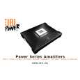
BP-150.1
1 Channel Automotive Amplifier
Features
1-Channel Operation Advanced MOSFET Oversized Floating Rail Power Supply Floating Ground Factory - Head - Unit Speaker - Level input Variable Input Sensitivity (250mV - 4V) Fully Complementary Output Stage with Class-D Gold-plated Power, Input and Output Connectors 1-Ohm Stable Voltage Amplification
Test Conditions and Notes
All tests to be done, unless otherwise specified, from 10Hz to 320Hz at 14.4V DC into 4 ohm loads and will be done using an Audio precision system one and the supply voltage.
the units gain so that with a .775 volt input signal the unit is at i's maximum rated output. All meas
An B+ line voltage of 14.4V DC shall be applied to the unit under test for all measurements unless oth
specified. The voltage applied to the unit shall be measured at the power connection on the Amplifier. Signal Source
Unless otherwise specified, all tests shall be conducted with the Audio Signal Generator output config connected to the Amplifier PWR GND at the Amplifier. Output Load
be balanced, less than or equal to 50 ohm source impedance, and floating. The signal source "GND" shal
Unless otherwise specified, all tests shall be conducted with 4 ohm resistive loads having less than 1 while dissipating the rated output of the unit under test.
reactive components at any frequency below 350KHz. Each resistor shall have a value that remains withi
Power Indicator Green LED steadily illuminates for normal operation. Illuminates up Red LED blinks whe protection circuitry is engaged, and during power up.
2
|
|
|
> |
|